S14 digital climate control install
NOTES
- Any text that looks like this is a warning. Please read and understand them before working on this project!
- Any text that looks like this is a comment on how I chose to do something. I'm sure I didn't do things the best way but I got them done.
Thanks to Russ, Ken, and R&D Factory for the help in figuring all this out. Also, thanks to the guy who sold me everything on eBay.
TIME NEEDED
Took me about 1 week of researching, 2 months of lagging, another 1 week of preparation, and 15-20 hours of mounting/wiring.
ITEMS NEEDED
Donors
Some of the parts below are available off of multiple cars which I will call donor cars. These are:
- Mid-90s Maxima with DCC
- Mid-90s Altima with DCC
- JDM S13 or S14 with DCC
Required parts
I found this forum post about an Altima DCC install and it looks like all of the parts should work for the S14 so I'm including the Nissan part numbers for Altima (and some Maxima) donor parts. I can't guarantee that all of the parts will work since I haven't tried them. If you've tried them and they work, then let me know and I'll put a note here. The Altima and Maxima parts look the same so as long as they work the same electronically (which I think they do), they should work. There aren't any reserved spaces in the USDM S14 for the parts below (except for the control unit and the sunload sensor), so it won't matter too much if they're not the exact shape and size as the JDM S14 parts. Anyway, the safest bet is to go with a JDM S13 or S14 as the donor since those will work for sure.
- JDM digital climate control (DCC) unit with the two subharness plugs and at the minimum 2" of wires (from a JDM S14 only)
- Sunload sensor (any donor, Altima/Maxima part no. 27721-0E000)
- Ambient temp sensor (any donor, Altima part no. 27722-0E000, Maxima part no. 27710-31U00)
- In-cabin temp sensor (any donor, Altima part no. 27720-0E000, Maxima part no. 27720-31U00)
- Fan control amp (any donor, Altima part no. 27761-85E01)
- Fan control amp mounting shield (any donor except the JDM S14, Altima part no. 27152-0E000)
- With the JDM S14 mounting shield, the fan control amp will not sit as deep into the cooling unit so it will prevent the glovebox from closing.
Optional parts
- Ambient temp sensor mounting bracket (Altima part no. 27715-0E000)
- I didn't have an ambient temp sensor mounting bracket but it looks like I needed some sort of bracket to make it work. The part number above is for the Altima bracket so I'm not sure if that'll fit the S14.
- Aspirator (any donor, Altima part no. 27726-0P000)
- The aspirator is used to suck cabin air over the in-cabin temp sensor. You don't really need it if you mount your sensor in a good location.
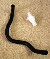
- Aspirator hose (Altima part no. 27727-1E400)
- I ordered the aspirator hose with the part number above but it didn't seem to fit well in the S14. A safer bet would be to just buy a hose of the right size and length and fit it to your car. I didn't get a chance to measure the diameter of the hose but I will update this page when I get that info.
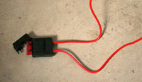
- Inline fuse holder and 7.5A fuse
- Something like the one below from Radio Shack. Holds a blade-type fuse to protect your DCC unit.
- Complete JDM DCC subharness
- Having the complete subharness will make things a lot easier or a lot more difficult, depending on how much you like running wires versus how much you like taking apart your dashboard.
- The USDM S14 FSM and the SR20DET S14 FSM
- With the FSMs, you'll be able to look up anything I missed. The wiring diagrams and component drawings helped a lot. You'll also want the SR20DET FSM for information on any programming/debugging you want to do with the DCC.
Tools
- Soldering iron, solder, wires, crimping tools, etc.
- Dremel, utility knife, etc.
- Electric tape, heatshrink, etc.
- Almighty zipties
DESCRIPTION
Here is a list of the parts that are involved with the climate control system and a description of each part:
- Air mix door: This door controls how much cold air and how much hot air is blown out the vents. It's located above the gas pedal, on the left of the heating unit.
- Intake door: This door controls how much air is drawn from outside and how much air is drawn from the inside of the car. It's located above the blower motor behind the glovebox, to the right of the cooling unit.
- Bi-level door motor: This motor allows both the vent door and foot door to be open at the same time. It's located behind the glovebox, to the left of the cooling unit.
- Mode door motor: This motor controls which vents the air blows out of (face, floor, defrost). It's located above the air mix door motor, behind the head unit.
- Blower motor: The blower motor controls how much air is being blown. It's located behind the glovebox, to the right of the cooling unit.
- Thermo control amp: This amp controls whether or not the A/C compressor is turned on by detecting the temperature inside the cooling unit. It's a black rectangular block mounted on the right of the cooling unit and has a wire that runs into the cooling unit to a thermistor.
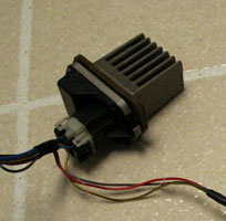
- Fan control amp: This amp tells the blower motor how much air to blow. It should be installed into the left of the cooling unit with its mounting shield.
- In-cabin sensor: This sensor detects the temperature inside the car. The stock location would be to the right of the steering wheel, where the cruise control button is but you can really mount it anywhere that would allow the sensor to pick up a good temperature reading.
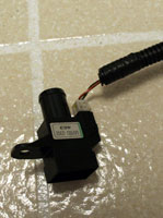
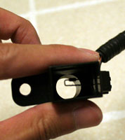
- Ambient sensor: This sensor detects the temperature outside of the car. It should be mounted in the front of the car, under the hood.
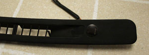
- Sunload sensor: This sensor detects how much light is shining into the car. It should be mounted into the passenger side of the windshield vent trim piece.
- Aspirator: This device creates a vacuum and is connected to the in-cabin sensor so that cabin air will pass over the sensor. The stock location is above the bi-level door motor, mounted into the heating unit.
- Digital control unit: This is the brain of the digital climate control. It is mounted in place of the original control unit in the dashboard.
MOUNTING
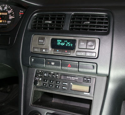
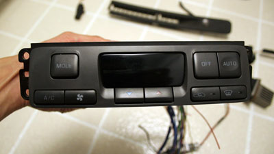
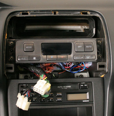
Digital climate control (DCC) unit
- Push in the bottom of the middle vents and get a grip on that section.
- Pull down and out to detach top of the trim from two clips at the top.
- Use a finger or a covered flat head screwdriver to pull on the bottom and detach the two clips there.
- Pull the trim out and disconnect the plugs for hazard light and rear defroster.
- Unscrew the old unit which is attached by four Philips screws.
- Screw in the new unit when you're done with all the wiring, plug the hazard light and rear defroster back, push the trim back, and snap in the clips.
Sunload sensor
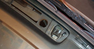
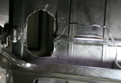
- Use a flat head screwdriver to pry up the windshield vent trim on the seat side (not the window side). There are tabs on this side that are supposed to come up (correct me if I'm wrong). Notice that there's a hole in the passenger side of the main dashboard piece. That's where the sensor sits in. Be very careful because this piece is very brittle in our 12+ year old cars. The trim piece is super fragile! I tried to be careful taking the piece off but all my tabs as well as a couple of the dividers broke off. Below is a picture of the hole in the dashboard
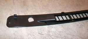
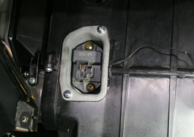
- On the bottom side of the vent trim piece, you'll notice there is a hole on either side of the vents. Cut a hole for the sensor on the passenger side hole. The hole is shaped like a circle but with one side flat. Be careful when cutting your hole. I broke my piece in half and then some. I had a partial JDM trim piece that I was able to use as a template for my hole so my sensor snaps in nicely. Below is a picture of the underside of the JDM trim piece to give you an idea of the shape, size, and location of the hole. It is on the opposite site for the USDM piece though.
- Run two wires from the DCC unit to sensor location, solder them to the plug, put back the trim piece, connect the plug to the sensor, and snap the sensor into the hole. To run the wires, I fished a wire hanger down the top hole towards the right, over the intake unit and pulled the wire up. Since I broke all the tabs on my trim piece, it just sits there with no support. There's no movement or rattle at all though.
Ambient temp sensor
- Run two wires from your DCC unit to your hood latch area.
- Solder the wires, plug in the sensor, and mount it. My sensor had a broken mounting tab so I just ziptied it to the hole on the frame support rail. I think there's supposed to be a bracket that attaches the sensor to the frame but I didn't have that.
In-cabin temp sensor
- Choose a place to mount the sensor and work with what you have to get it mounted. The sensor is supposed to have a mounting location where the cruise control button is. However, the sensor doesn't fit there and also, if you have cruise control, then you need that location for the button. I didn't include a picture of my setup because I haven't decided on a good place to mount it with good airflow and an accurate reading.
- You should have vent holes in front of the sensor to allow cabin air to pass over it so cut some if you mounted the sensor behind a cover.
- If you have an aspirator and hose, mount the aspirator onto the front of the heating unit (white box behind DCC unit/radio) and connect the aspirator to the sensor housing with the aspirator tube. I just found the only flat surface on it that would fit the aspirator and attached it with self-tapping screws about 1/2" long. Try to cut the hole nicely so air doesn't leak out.
- Run two wires from the DCC unit to your location, solder the wires, plug in the sensor, and finish mounting the sensor.
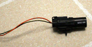
Fan control amp (AKA blower motor speed sensor)
- Make a template so you can cut a hole with the right shape and size to fit the mounting shield into the cooling unit (AKA evaporator) (minus the edges, of course).
- Remove the glovebox (two screws at the bottom) and the glovebox frame (four screws around it).
- The mounting shield sits on/in the cooling unit (black box on the left behind the glovebox). Cut the hole as far to the left as possible. Vertically, it should be centered on the "equator" on the cooling unit. I used a dremel but it got little pieces of plastic into the cooling unit. I was able to cut some lines with a utility knife so you might want to go that.
- Mount the shield onto the cooling unit. (I used self-tapping screws about 1/2" long. I guess you could use glue or double-sided tape but the screws work for me.)
- Mount the fan control amp inside the shield.
- Run wires according to the wiring section.
WIRING
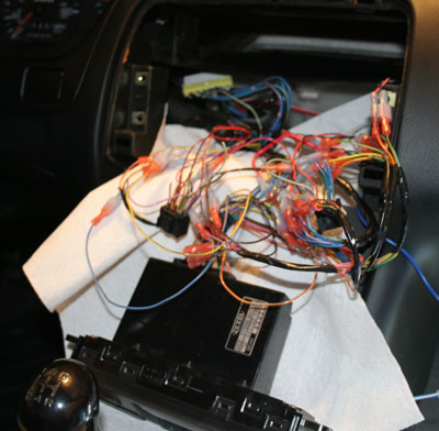
The JDM DCC unit has 2 connectors on the back: one with 20 wires and another with 16 wires. The USDM control unit has 3 connectors on the back: one with 12 wires, another with 16 wires, and finally a 6 wire connector for the fan switch. Obviously you won't be able to just plug and play. If you have the complete JDM DCC subharness, you basically just pull out the USDM subharness, lay in the JDM one, plug everything in and go. The only problem is that the USDM air mix door motor's plug is different but it has the same wires so you should be able to just repin it with info from the FSMs. There's probably a little more to it than that but nothing too difficult.
If you're unlucky and don't have the subharness, then you're lucky because you'll have to do a lot of soldering/crimping. What I did was follow the table below, pick a wire to connect, find the wire on the USDM plug, cut it, and attach it to the JDM plug. How you do that is your preference. What I did was crimp on female disconnects to all of the JDM wires, then as I cut the USDM wires, I crimped on male disconnects and partially connected them. This way, if I messed up, I could rearrange the wire connections easily. The crimping took forever and the connectors take up a lot of space and can rattle against things, but I felt more comfortable knowing that I could rearrange the wires without losing wire length due to soldering (desoldering is too much of a hassle).
Abbreviations:
- FS = fan switch (secondary plug on USDM control unit)
- BM = blower motor (the plug at the front bottom of the black round box to the right of the cooling unit)
- ICS = in cabin sensor
- SS = sunload sensor
- AS = ambient sensor
- FCA = fan control amp
- AMDM = air mix door motor
- TT = thermal transmitter
Colors:
- B = black
- G = green
- L = blue
- LG = light green
- OR = orange
- P = pink
- PU = purple
- R = red
- W = white
- Y = yellow
| JDM # | JDM color | USDM # | USDM color | Purpose/notes |
| 1 | R/B | 18 | PU | -OPEN/+CLOSE |
| 2 | R/Y | 19 | LG/W | +OPEN/-CLOSE |
| 3 | G/W | 11 | G/W | +FRE/-REC |
| 4 | G/B | 20 | G/B | -FRE/+REC |
| 5 | G/Y | 8 | G/Y | +DEF/-VENT |
| 6 | G | 7 | G/OR | -DEF/+VENT |
| 7 | R/G | 22 | L/R | +HOT/-COLD |
| 8 | R | 23 | R/W | -HOT/+COLD |
| 9 (9) | L | FS1 and FCA1 | L and L | FAN F/B |
| 10 | L/Y | FCA2 | L/Y | FAN OUT |
| 11 (1) | OR/G | 12V | - | BAT |
| 12 | L/OR | 14 | L/OR | IGN |
| 13 | R/L | 15 | R/L | +ILL |
| 14 (7) | B | 17 | B | -ILL (GND) |
| 15 | - | - | - | -nothing- |
| 16 (2) | L/W | BM2 | L/W | IGN (+FAN) |
| 17 (3) | Y | TT1 | Y | WATER TEMP |
| 18 | - | - | - | -nothing- |
| 19 | Y/B | 13 | Y/B | A/C SIGNAL |
| 20 (7) | B | 17 and FCA3 | B and B | GND |
| 21 | L | 5 | L/B | MODE 1 |
| 22 (4) | L/R | 1 and 4 | L/OR and L/W | MODE 3 |
| 23 (8) | G/Y | - | - | INTAKE 2 |
| 24 (7)(8) | Y | 17 | B | INTAKE 3 |
| 25 | OR/L | ICS1 | OR/L | IN CABIN SENSOR |
| 26 | OR | SS1 | OR | SUNLOAD SENSOR |
| 27 | P/L | 26 | P/L | PBR |
| 28 (8) | Y/R | - | - | INTAKE 4 |
| 29 (5) | B/Y | ICS2, AS2, SS2 | B/Y | SENSOR GND |
| 30 (4) | L/W | 3 and 6 | L/R and L | MODE 2 |
| 31 | L/B | 2 | L/Y | MODE 4 |
| 32 (8) | Y/B | - | - | INTAKE 1 |
| 33 (6) | P | AMDM3 | L/OR | +5V (PBR) |
| 34 | OR/B | AS1 | OR/B | AMBIENT SENSOR |
| 35 | - | - | - | -nothing- |
| 36 | - | - | - | -nothing- |
- (1) Wire 11: This wire should go to a constant 12V source with a 7.5A fuse (see optional parts above). I think this is so the DCC unit will remember your settings after you turn off the car. I ran this to the ignition 12V (white wire) but you can pull it from wherever you feel comfortable, like maybe the head unit.
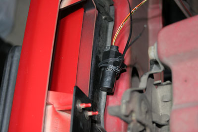
- (2) Wire 16: I'm not sure you have to get this from the blower motor but the wiring diagrams in the SR20DET FSM showed it so that's how I did it. The easiest way to get to this wire is to run a wire to the plug at the blower motor. The target wire is the taped up wire next to the blue one in the picture.
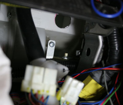
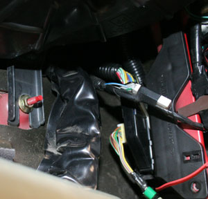
- (3) Wire 17: This wire is connected to the thermal transmitter wire which goes to the water temperature gauge in your cluster. You can either get to the wire behind the gauge cluster or at the F3/M63 connection in the passenger kick panel. I did the F3/M63 connection which is wire 28. The connection is behind the ECU. I can't really remember how I did it but it's the red wire in the picture. I think I had to take out that black plastic holder. You should probably just wire this to the gauge cluster.
- (4) Wires 22 and 30: Each of these wires will be connected to two wires from the mode door motor.
- (5) Wire 29: This wire will be connected to all 3 of the ground wires from the 3 sensors.
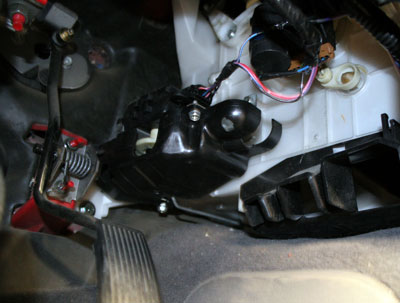
- (6) Wire 33: This wire goes to a +5V source and the easiest one I found was at the air mix door motor. The picture below shows the air mix door motor which is above the gas pedal. The target wire is the blue looking wire by itself (it's really blue/orange).
- (7) Wires 14, 20, and 24: These 3 wires will share a connection to the existing ground wire. You'll also need to ground the fan control amp so I just connected it here too.
- (8) Wires 23, 24, 28, and 32: The wiring above is the easy way to wire the intake door motor. It will make the RECIRCULATE button work but you will be losing out on the 20% fresh intake door position. The problem is that there are 6 pin positions on the plug for the intake door motor (2 for moving the motor and 4 for detecting the door's position) and while the JDM S14 has all 6 positions filled with wires that run to the control unit, the USDM S14 only has 4 wires. The 4 door positions are full fresh, 20% fresh, 20% recirculate, and full recirculate. The USDM plug only has wires connected to the full fresh and full recirculate pins. If you have the JDM DCC subharness, then you're fine. Otherwise, you'll have to run 2 wires to the plug in order to receive those two extra signals. The bad news is that the plug is impossible (at least for me) to get to without taking off the dash because it's located near the top of the intake door. I decided to try all combinations of using the 2 wires that were there to connect to the 4 intake wires on the DCC unit and nothing worked. Either the door wouldn't move when I switched between fresh and recirculate, or it would just go to one end and keep turning the motor. I then tried grounding some of the wires to see if I could trick the unit. At first I tried combinations of having all 4 intake wires connected but then just tried grounding one wire at a time with all other wires disconnected. With just intake 3 grounded, I was able to switch between fresh and recirculate correctly. Using the diagnostics mode (explained below), I could see that the DCC unit couldn't properly detect the door positions. However, when it tried to go into the positions, it worked so I was happy.
- (9) Wire 9: This wire should be connected to one of the fan control amp wires and also to one of the wires from the fan switch plug. The fan switch plug is the ugly 6 wire plug that went into the USDM control unit.
TROUBLESHOOTING
Diagnostics mode
This is just a summary of what is in the SR20DET FSM. To enter the diagnostics mode, press and hold the OFF button for 5 seconds within 5 seconds of turning the key to the ON position. You'll start in screen 1 and can go up to screen 2, 3, 4, and 5 by pressing the red UP button. You can go back down a screen by pressing the blue DOWN button.
- You'll start off in screen 1 which will light everything up on the screen so you can see if anything isn't lighting up properly.
- When you go into screen 2, the unit will test to see if it is receiving a valid reading from each of the three sensors. The sunload sensor will fail unless it has a decent amount of light shining on it. After a few seconds, you'll see a flashing error code.
| Error code | Reason |
| 20 | Everything is good |
| 21 | Problem with ambient sensor |
| 22 | Problem with in-cabin sensor |
| 25 | Problem with sunload sensor |
| 26 | Problem with air mix (hot/cold) motor |
- When you go into screen 3, the unit will test all of the motors so you'll here everything moving. After a few seconds, you'll see a flashing error code.
| Error code | Reason |
| 30 | Everything is good |
| 31 | Problem with mode door (VENT) |
| 32 | Problem with mode door (BI-LEVEL) |
| 33 | Problem with mode door (FOOT) |
| 34 | Problem with mode door (FOOT/DEFROST) |
| 35 | Problem with mode door (DEFROST) |
| 36 | Problem with intake door (FRESH) |
| 38 | Problem with intake door (20% FRESH) |
| 39 | Problem with intake door (RECIRCULATE) |
If you followed the easy wiring for the intake door motor, then you will see errors 36, 38, and 39.
- When you go into screen 4, it will display a 41 on the screen. You can press the DEF button to advance to 42, 43, 44, 45, 46, and then loop back to 41. This screen sets each component to a certain command so that you can confirm things are working.
| Code | Mode door | Intake door | Air mix door | Blower motor | Compressor | Bi-level door |
| 41 | VENT | RECIRCULATE | FULL COLD | 4-5V | ON | OPEN |
| 42 | BI-LEVEL | RECIRCULATE | FULL COLD | 9-11V | ON | OPEN |
| 43 | BI-LEVEL | 20% FRESH | FULL HOT | 7-9V | ON | SHUT |
| 44 | FOOT | FRESH | FULL HOT | 7-9V | OFF | SHUT |
| 45 | FOOT/DEFROST | FRESH | FULL HOT | 7-9V | OFF | SHUT |
| 46 | DEFROST | FRESH | FULL HOT | 10-12V | ON | SHUT |
- Finally, in screen 5, you can see what the temperature readings are for the ambient and in-cabin sensors. Press the DEF button once to view the ambient reading. Press it again to view the in-cabin reading. Press it again to go back to the main screen.
- In screen 5, you can also press the FAN button to go into the "trimmer" mode. You'll see a 0 and can press the UP and DOWN buttons to go from -3 to +3 (in degrees C). What it does is compensate for the difference between the temperature the DCC senses and the temperature the driver feels. So if you feel cooler than what is set on the DCC, you'll want a positive number. If you feel hotter than what is set on the DCC, you'll want a negative number.
Discussion
If you'd like to discuss about this write-up, please visit this Zilvia forum thread.